Design Practice 16: Key Considerations for CAN Bus Application Design
The Controller Area Network (CAN) is a field bus technology developed by Bosch, essentially a serial asynchronous communication bus. It is widely used in automotive electronic control systems and industrial control scenarios.
Overview of CAN Bus
The CAN bus is similar to the RS485 bus in that both use differential signal lines for transmission. The two signal lines in CAN are CAN_H and CAN_L, which have equal signal amplitudes but opposite phases. The voltage difference between these two lines represents logic levels:
- A positive voltage difference indicates logic 0.
- A zero (or negative) voltage difference indicates logic 1.
Compared to RS485, the CAN protocol is more complex. While RS485 typically uses the UART module in an MCU, CAN requires a dedicated CAN controller. If the MCU does not have a built-in CAN controller, an external CAN controller chip is needed.
Typical CAN Bus Implementation
A CAN bus system typically consists of:
- MCU (Microcontroller Unit)
- CAN controller
- CAN transceiver
Below is a typical transceiver interface circuit for a CAN bus system:
(Note: The diagram mentioned in the original text is not included here.)
CAN Bus Standards
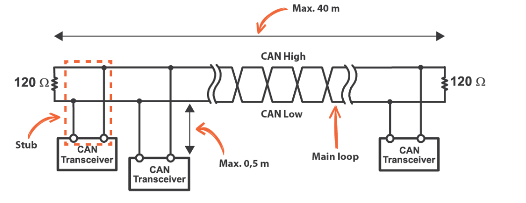
The CAN bus has evolved into two international standards: ISO11519 and ISO11898. Their key differences are as follows:
- ISO11898 (High-Speed, Short-Distance Closed-Loop Network):
- Maximum bus length: 40 meters
- Maximum communication speed: 1 Mbps
- Requires a 120-ohm termination resistor at each end of the bus.
- ISO11519-2 (Low-Speed, Long-Distance Open-Loop Network):
- Maximum transmission distance: 1 km
- Maximum communication speed: 125 kbps
- Each bus line requires a 2.2 kΩ series resistor. The two lines are independent and do not form a closed loop.
Practical Design Considerations
When designing a CAN bus system, the wiring method depends on the characteristics of the MCU’s CAN controller. For example, the STM32F103 microcontroller has the following CAN controller features:
- Supports CAN2.0A and CAN2.0B protocols.
- Communication speed up to 1 Mbps.
- Classified as a high-speed bus.
Thus, when designing the peripheral transceiver circuit for the STM32F103, the termination resistor configuration should follow the ISO11898 standard (i.e., 120-ohm resistors at both ends of the bus).
Conclusion
The CAN bus is a robust and reliable communication protocol widely used in automotive and industrial applications. Its design requires careful consideration of the specific standard (ISO11898 or ISO11519) and the characteristics of the MCU and transceiver components. In the next installment, we will focus on analyzing the details of the CAN protocol itself.
